4-minute read - by Christine Middleton, March 29, 2023
A single microchip in your smartphone or laptop is made up of dozens of layers of circuitry. For the chip to work properly, all of those layers have to be aligned with nanometer-level precision.
Lithography systems – the machines that print microchip patterns on silicon wafers – try to make sure that each chip layer sits perfectly on top of the previous one. In deep ultraviolet (DUV) lithography systems such as those made by ASML, the pattern for each layer is encoded in light and transmitted to the wafer using a series of lenses. Those lenses are incredibly smooth, but they still have tiny imperfections that can slightly distort the pattern being printed.
If those distortions change at all from one layer to the next, then the layers don’t quite line up. That misalignment can negatively affect a chip’s performance. It can even stop the chip from working altogether – a situation that chipmakers desperately want to avoid.
When chipmakers measure misalignment on their wafers, they adjust their lithography systems to correct for it. But chipmakers are now able to detect subnanometer-scale errors that available systems aren't able to correct for – they simply can’t make such tiny adjustments.
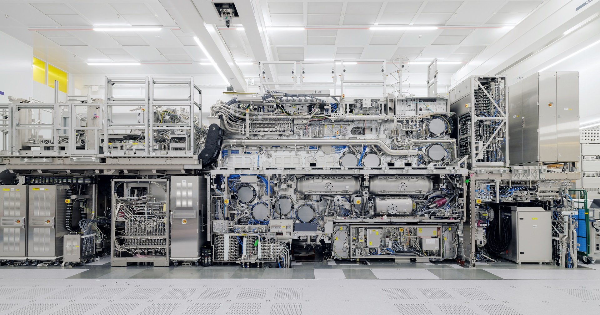
ASML teamed up with ZEISS, our strategic partner and maker of lenses for our lithography systems, to develop a solution: an improved lens-adjustment system. The new hardware and software upgrades, which are now fully integrated into ASML’s TWINSCAN NXT:2100i, provide chipmakers with unprecedented correction capability.

Lithography, lenses and layers
How well the layers of a microchip are aligned is called overlay. Optimizing overlay isn’t as simple as moving a wafer around to make sure it’s placed at exactly the right spot before printing starts – although that’s one part of it.
Another important consideration is that an imperfection in a lens might distort a particular area of the pattern being printed. And how exactly the pattern is distorted might change depending on where on the wafer it’s being printed. Over time the light used to print the pattern can also cause certain parts of the optics to heat up, which unevenly aberrates the light passing through.
Because the distortions that cause overlay problems aren’t static, the corrections can’t be either. That’s why the optics used in DUV lithography systems to project light onto wafers have lots of dynamically adjustable manipulators and stages.
The lithography systems use measurements of printed patterns to figure out what adjustments are needed. Those measurements can come from either the lithography systems themselves or from other machines, such as ASML’s YieldStar products, which are specifically designed to help chipmakers optimize overlay. The lithography system then uses the measurements to intentionally distort the image being printed. The intentional distortions are designed to correct the unintentional ones.
Challenges to improved precision
The new lens-adjustment system developed by ASML and ZEISS consists of many individual manipulators that adjust the lithography machine’s lenses. With that level of control, chipmakers can make their intentional distortions smaller – which means they can correct smaller misalignments.
Along with hardware upgrades, getting better correction resolution also requires software improvements. The software determines the locations of overlay errors by dividing the measured wafer image into a grid. The error’s location is identified by the grid space that it’s located in.
The new software divides each wafer into a grid that’s four times denser. By using more and smaller grid spaces, it can find smaller errors and instruct the hardware to correct for them.
Multiplying the number of grid spaces by four also means a four-fold increase in the amount of data that the software has to handle. So the software engineers working on the project had to speed up the computations. The new system can now analyze the larger amount of data it produces fast enough to keep up with the printing process and maintain the lithography system’s productivity.

A promising prototype
Tests on a prototype optics manipulator system at ASML delivered promising results. In one test, a lithography system was given a pattern to print. The lens manipulator was then asked to intentionally distort that pattern by introducing specific errors. The sizes of the errors produced on the printed wafer were within 10% of the requested sizes. So if a distortion was meant to be about 0.5 nm, it was accurate to less than 0.1 nm.
In a second test, two layers were printed on a wafer. Then the mismatch between the layers was measured and the system was asked to correct for it. With the correction, the size of the mismatch shrunk from about 0.65 nm to about 0.3 nm – almost as small as a single silicon atom.
After working with its own prototypes, ASML delivered lens-manipulation systems to customers for testing in their facilities. The customer feedback helped ensure that any remaining bumps got smoothed out. Chipmakers are starting to introduce the lens system into high-volume microchip manufacturing, starting with the TWINSCAN NXT:2100i.
Enabling tomorrow’s technology
In addition to aligning layers printed using the same machine, the lens manipulator will also improve overlay of layers that are printed using different machines. Every lithography system is slightly different and produces a unique ‘distortion fingerprint’. The fingerprint for the machine that prints one layer can be measured and communicated to the machine that will print the next layer. The second machine can then correct for overlay errors caused by the first one.
But why use more than one lithography systems to print a single wafer? The features in the different layers are different sizes. The first few layers have the smallest features, so those need to be printed using the newest systems with the best resolution. Larger features in the upper layers can then be printed using established technology.
In the future, more and more cutting-edge chips will have their first few critical layers printed using ASML’s extreme ultraviolet (EUV) lithography systems. But higher layers will still be printed with DUV systems. So by smoothing machine-to-machine wafer transitions, the new lens manipulator will help chipmakers make state-of-the-art technology a reality.